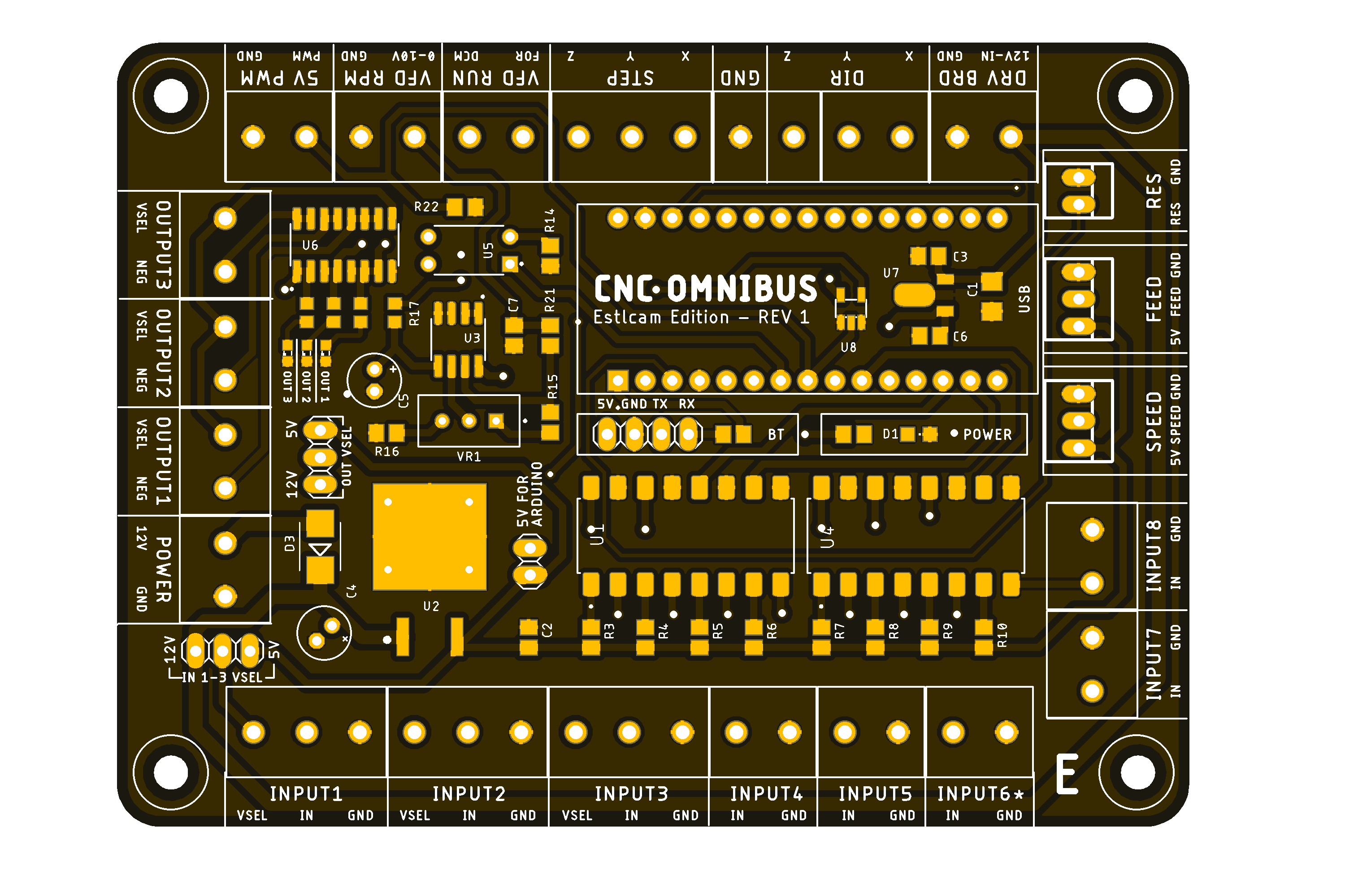
CNC Control Project (GRBL and ESTLCAM based). Please dont' sell the boards published here without my consent.

• 8 inputs for sensors and buttons (IN6 is usable if you remoove the LED "L" from the Nano)
• All inputs are isolated with optocouplers
• Inputs 1-3 have selectable voltage (5/12v) so you can connect inductive proximity sensors directly
• VFD outputs (Spindle ON/OFF and RPM control)
• 5V PWM output
• 3 Outputs for relays - the outputs have selectable voltage (5/12v) - OUT3 is automatically enabled on spindle ON
• Feed/Speed override connectors (JST XH 3P)
• Header for bluetooth serial module (HC-05)
• Screw-Terminals for easy connection
• Connector for the DRV-Shield

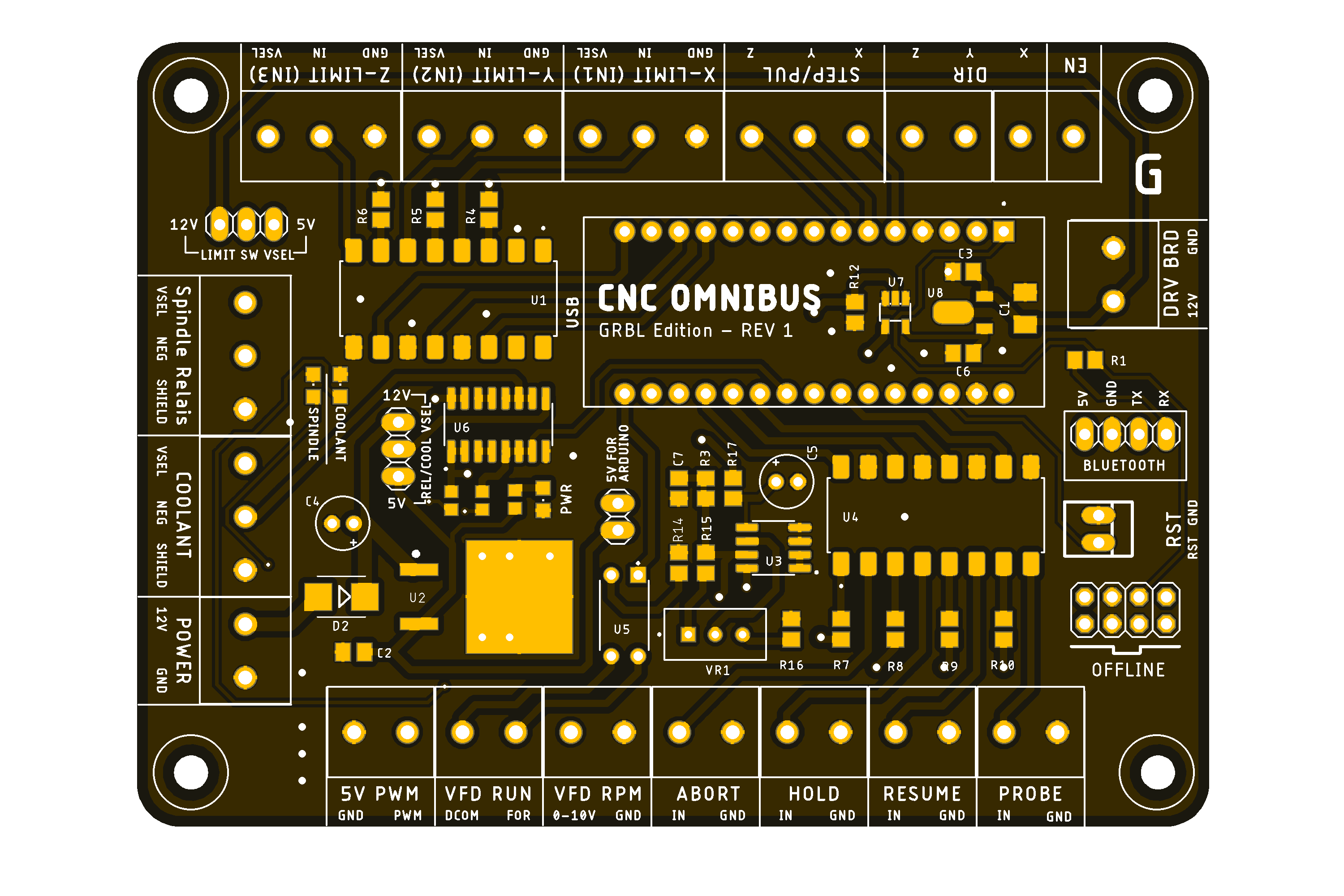
• Limit-Inputs XYZ have selectable voltage (5/12v) so you can connect inductive proximity sensors directly
• ABORT/HOLD/RESUME/PROBE inputs
• All inputs are isolated with optocouplers
• VFD outputs (Spindle ON/OFF and RPM control)
• 5V PWM Output
• 2 Outputs for relay (SPINDLE_RELAIS / COOLANT) - the outputs have selectable voltage (5/12v) - SPINDLE RELAY is automatically enabled on spindle ON
• Header for bluetooth serial module (HC-05)
• Header for offline controller
• Screw-Terminals for easy connection
• Connector for the DRV-Shield
NOTE: To use the "SPINDLE RELAY" and "VFD RUN" Outputs, please uncomment "define USE_SPINDLE_DIR_AS_ENABLE_PIN" in the GRBL config.h file.

• Up to 10A current support (2oz copper PCB required)
• 3-Axis stepper driver support (DRV8825/S109/TMC2100) with stepping config jumpers
• Header for laser module (3p)
• Laser module safety switch - PWM controlled
• Header for an extra 12V 2A BEC to power a laser module (20w max)
• 12V fan header
• 12V Power supply for the OMNIBUS controller (so you don't need an extra 12v PSU for the controll board)
• Screw-Terminals for easy connection
NOTE: If powerting the OMNIBUS Controller with the DRV Shield, use a heatsink on the 12V LDO and provide good airflow - the LDO is getting hot and will shut down if thermal protection kicks in.