This is a library and example code with which one can controll multiple rotary encoders over the MCP23017 I2C GPIO expander.
The basic idea is that rotary encoders are either polled or read using interrupts.
When polling:
- read the state of all GPIO pins
- feed this as input to the rotary encoder library
When using interrupts:
- activate
CHANGEinterrupts on all inputs - setup the MCP23017 to OR the
INTA(interrupt on GPIO Bank A) andINTB(GPIO Bank B) together on both pins- thus uses only one interrupt pin is used
- when an interrupt occurs, sets a boolean flag
- main code will check for flag, if it set will read registers and update encoders
Include the RotaryEncOverMCP.h header in your project.
This exposes a RotaryEncOverMCP which can be constructed by using a reference to an Adafruit_MCP23017 object, its two pin numbers for encoder output A and B. Can also optionally receive an ID and a callback function which will be called when there is a clock-wise or counter-clock-wise rotation of the encoder. The callback is then called with a boolean flag (clockwise rotation or not) and its previously given ID.
class RotaryEncOverMCP {
	RotaryEncOverMCP(Adafruit_MCP23017* mcp, byte pinA, byte pinB, rotaryActionFunc actionFunc = nullptr, int id = 0);

	/* Initialize object in the MCP */
	void init();

 	/* On an interrupt, can be called with the value of the GPIOAB register (or INTCAP) */
	void feedInput(uint16_t gpioAB);

	/* Poll the encoder. Will cause an I2C transfer. */
	void poll();

	Adafruit_MCP23017* getMCP();
};The following modifications to the libraries were made
- Adafruit MCP23017: Added the
uint16_t readINTCAPAB();function for reading the interrupt capture registers (state of the GPIO pins at the moment the interrupt occured) - Rotary: Added
unsigned char process(unsigned char pin1State, unsigned char pin2State);so that it internally doesn't have to do thedigitalReaditself but can be controlled from the outside
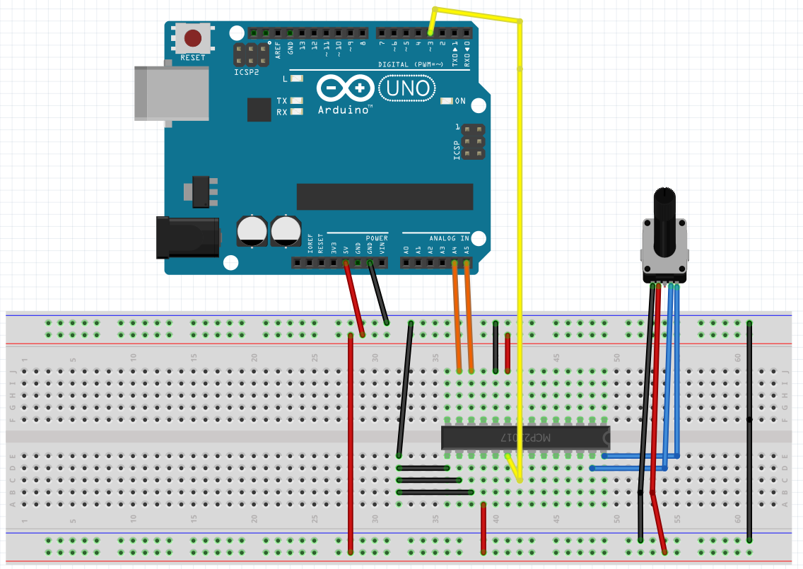
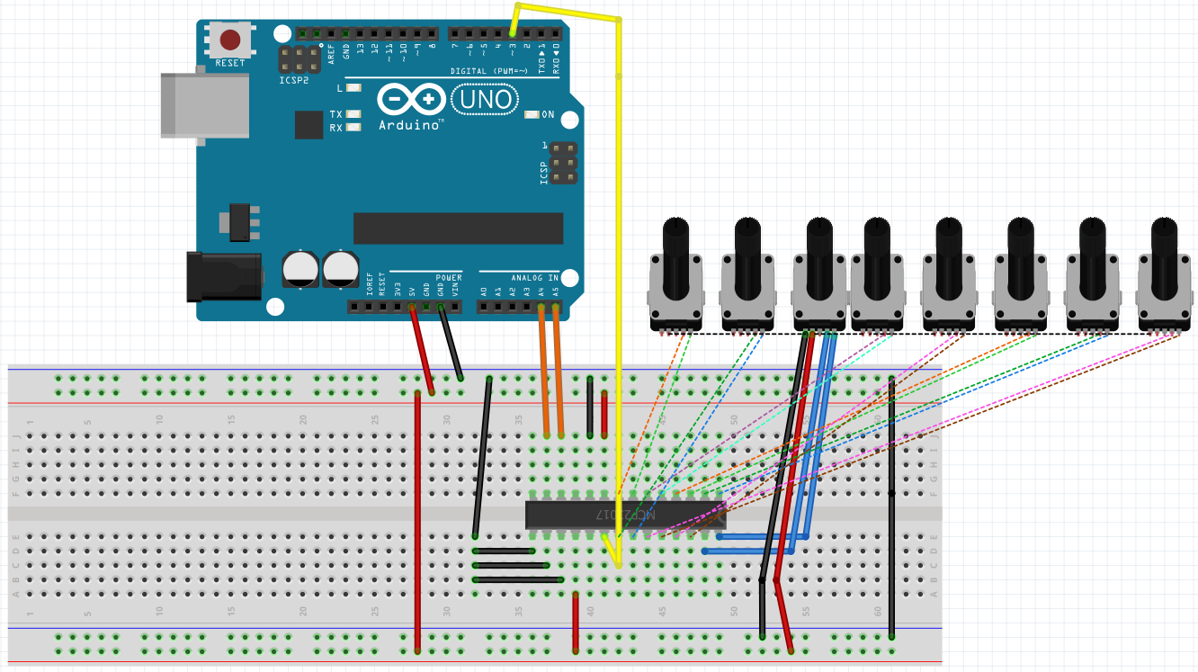
Schematics can be found in the "Images" folder.
Using 1 encoder + 1 MCP23017 :
Using 8 encoders + 1 MCP23017:
Since MCP23017 has a 3-bit modifyable address, there can be 2^3 = 8 devices on one I2C bus (= 128 GPIO ports). With each device having 16 inputs and each encoder needing 2 inputs, this yields a maximum of 8 * 16 / 2 = 64 rotary encoders. One can use a software I2C bus and 2 free pins to further increase this number.
The example sketches are already made for such a case by specifying a list of Adafruit_MCP23017 objects. When using interrupt-based reading, you must OR all interrupt lines together to one (e.g. by using a diode-OR or a CMOS OR gate).
Written by Maximilian Gerhardt. Based on the Arduino stackexchange question by Andrew Lazarus: https://arduino.stackexchange.com/questions/52909/reading-several-rotary-encoders
Since this project contains the Rotary project wich under GPLv3, this project's code is under GPLv3, too.

