This code allows for control of a Reverse Osmosis system based on up to two float switch inputs, as well as a single button momentary switch for selecting the operational state.
- System states: Enable RO (or automatic mode), Force RO (ignore float inputs), Off'
- Pump States: Idle (enabled, but not running), On (running from automatic mode), Force (Force RO is selected)
- Tank States: High, Low
- Inverse colors for none-optimal states:
- Force RO or Off System State
- Force Pump state
- High Grey tank level
- High Fresh tank level, but only when in Force RO System state.
- YouTube Video Demo
- Amazon link for Arduino Nano
- Amazon link for OLED Displays
- Amazon link for Relay
- Instructions on getting the Adafruit GFX library installed
| Arduino Pin | Destination |
|---|---|
| 5v | Relay + |
| 3.3v | OLED Display Vcc |
| GND | Common Ground |
| A4 | OLED Display SDA |
| A5 | OLED Display SCL |
| 2 | Fresh Tank Float Switch (to Common Ground) |
| 3 | Grey Tank Float Switch (to Common Ground) |
| 4 | Momentary Switch for changing mode (to Common Ground) |
| 5 | Relay board 'S' pin |
Note: The Common Ground will be connected to the following items:
- OLED Display GND pin
- Relay board '-' pin
- Momentary Switch 2nd pin
- Float switch 2nd pins
The Arduino can be powered via USB, or through the Vin pin (by 6 to 12vdc).
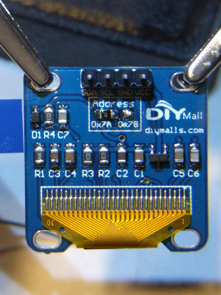
Also of interest... In order to use two of the OLED displays on the same I2C bus, you'll need to be a bit handy with a soldering iron. On the rear of the display, there's a small SMD jumper soldered across the right hand 'Address' pins (labeled 0x78, although the actual I2C address is 0x3C). On one display, you'll need to de-solder the jumper, and move it to the left side 'Address' pins (labled 0x7A, again, wrong.. it's actually at 0x3D).
Here's a picture of the jumper in the 0x7A ( 0x3D address ) position:
