-
Notifications
You must be signed in to change notification settings - Fork 25
Stepper Motor
##Stepper Motor Demo
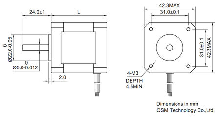
In this tutorial, we'll model a NEMA 17 stepper motor. The Nema motor is a de facto standard for the reprap project and modeling it is a first step towards designing your own printer parts.
So let's start with the specs:
We need a box that's 42mm x 42mm in size.
box([42,42,42], anchor=[0,0,-1]);

Stack on top of that a clearance for gears that's 22mm in diameter and set it to whatever height sounds reasonable.
box(42)
align(top)
rod(d=22,h=10);

Now the screws. Screws are set 31mm apart, so position a rod at half this distance from the center along the x and y axes. We'll use translated to do it in all four corners of the motor.
box(42)
align(top)
{
	rod(d=22,h=10);

	translated(31*y, [-1,1]/2)
	translated(31*x, [-1,1]/2)
	rod(d=3,h=7);
}

##Screw Heads
We now have a pretty functional model for most practical purposes. Well, that was easy. Feels like this tutorial should have gone on longer. For the hell of it, let's put some heads on our screws.
box(42)
align(top)
{
	rod(d=22,h=10);

	translated(31*y, [-1,1]/2)
	translated(31*x, [-1,1]/2)
	rod(d=3,h=7)
	align(top)
	rod(d=6,h=2);
}

Add some screw slots, too. Here we need to perform a difference, but we can't just call difference because the screw slots are going to be the children of the screw heads. Instead, we'll assign the screw slots as negative space and use relativity's CSG operations to take the difference between positive and negative spaces.
box(42, $class="+")
align(top)
{
	rod(d=22,h=10);

	translated(31*y, [-1,1]/2)
	translated(31*x, [-1,1]/2)
	rod(d=3,h=7)
	align(top)
	differed("+","-")
	rod(d=6,h=2)
	align(top)
	box([4,1,1], anchor=top, $class="-");
}

Let's make it a Philip's screw. We'll use rotated to take the slot above and apply it in two different directions.
box(42, $class="+")
align(top)
{
	rod(d=22,h=10);

	translated(31*y, [-1,1]/2)
	translated(31*x, [-1,1]/2)
	rod(d=3,h=7)
	align(top)
	differed("+","-")
	rod(d=6,h=2)
	align(top)
	rotated(90*z, [0,1])
	box([4,1,1], anchor=top, $class="-");
}

Round out the screw heads. We'll split the screw head into two cylinders of different size, then use hulled("+") to take the hull on just the positive space.
box(42, $class="+")
align(top)
{
	rod(d=22,h=10);

	translated(31*y, [-1,1]/2)
	translated(31*x, [-1,1]/2)
	rod(d=3,h=7)
	align(top)
	differed("+","-")

	hulled("+")
	rod(d=6,h=1.5)
	align(top)
	rod(d=5,h=1)

	align(top)
	rotated(90*z, [0,1])
	box([4,1,1], anchor=top, $class="-");
}

##Rotor
Still not enough detail? Let's flesh out the rotor. Shorten the cylinder we modeled for the gear clearance and add a 5mm rotor shaft.
box(42, $class="+")
align(top)
{
	rod(d=22,h=1)
	align(top)
	rod(d=5, h=20);

	translated(31*y, [-1,1]/2)
	translated(31*x, [-1,1]/2)
	rod(d=3,h=7)
	align(top)
	differed("+","-")
	hulled("+")
	rod(d=6,h=1.5)
	align(top)
	rod(d=5,h=1)
	align(top)
	rotated(90*z, [0,1])
	box([4,1,1], anchor=top, $class="-");
}

Stick a gear on top.
box(42, $class="+")
align(top)
{
	rod(d=22,h=1)
	align(top)
	rod(d=5, h=20)
	align(top)

	translate(2*up)
	differed("+","-")
	rod(d=15, h=8, anchor=$outward)
	rod(d=5, $class="-");

	translated(31*y, [-1,1]/2)
	translated(31*x, [-1,1]/2)
	rod(d=3,h=7)
	align(top)
	differed("+","-")
	hulled("+")
	rod(d=6,h=1.5)
	align(top)
	rod(d=5,h=1)
	align(top)
	rotated(90*z, [0,1])
	box([4,1,1], anchor=top, $class="-");
}

Drill a hole in the gear and slide the shaft through it
box(42, $class="+")
align(top)
{
	rod(d=22,h=1)
	align(top)
	rod(d=5, h=10)
	align(top)
	translate(2*up)
	differed("+","-")
	rod(d=15, h=8, anchor=$outward){
		rod(d=5, $class="-");

		align(bottom)
		rod(d=17, h=1);

		rotated(360/20*z, [1:20])
		align(x)
		align(bottom)
		rod(d=1.75, anchor=$outward, $class="-");

	}

	translated(31*y, [-1,1]/2)
	translated(31*x, [-1,1]/2)
	rod(d=3,h=7)
	align(top)
	differed("+","-")
	hulled("+")
	rod(d=6,h=1.5)
	align(top)
	rod(d=5,h=1)
	align(top)
	rotated(90*z, [0,1])
	box([4,1,1], anchor=top, $class="-");
}

Now add some gear teeth and a belt catch
box(42, $class="+")
align(top)
{
	rod(d=22,h=1)
	align(top)
	rod(d=5, h=10)
	align(top)
	translate(2*up)
	differed("+","-")
	rod(d=15, h=8, anchor=$outward){
		rod(d=5, $class="-");

		align(bottom)
		rod(d=17, h=1);

		rotated(360/20*z, [1:20])
		align(x)
		align(bottom)
		rod(d=1.75, anchor=$outward, $class="-");

	}

	translated(31*y, [-1,1]/2)
	translated(31*x, [-1,1]/2)
	rod(d=3,h=7)
	align(top)
	differed("+","-")
	hulled("+")
	rod(d=6,h=1.5)
	align(top)
	rod(d=5,h=1)
	align(top)
	rotated(90*z, [0,1])
	box([4,1,1], anchor=top, $class="-");
}

#Decorations
Some models have a shallow well around the rotor. Let's draw that!
differed("+","-")
box(42, $class="+")
align(top)
{
	rod(d=35,h=0.25, anchor=$outward, $class="-")
	align(bottom)
	rod(d=22,h=2, anchor=$outward, $class="+")
	align(top)
	rod(d=5, h=10)
	align(top)
	translate(2*up)
	differed("+","-")
	rod(d=15, h=8, anchor=$outward){
		rod(d=5, $class="-");

		align(bottom)
		rod(d=17, h=1);

		rotated(360/20*z, [1:20])
		align(x)
		align(bottom)
		rod(d=1.75, anchor=$outward, $class="-");
	}

	translated(31*y, [-1,1]/2)
	translated(31*x, [-1,1]/2)
	rod(d=3,h=7)
	align(top)
	differed("+","-")
	hulled("+")
	rod(d=6,h=1.5)
	align(top)
	rod(d=5,h=1)
	align(top)
	rotated(90*z, [0,1])
	box([4,1,1], anchor=top, $class="-");
}

Other models have a fillet on their sides, so we'll add that too.
differed("+","-")
box(42, $class="+"){

	align([-y,y])
	align([-x,x])
	rotate(45*z)
	box([5,5,indeterminate], $class="-", anchor=center)
	box([10,10,20], anchor=center);

	align(top)
	{

	    rod(d=35,h=0.25, anchor=$outward, $class="-")
	    align(bottom)
	    rod(d=22,h=2, anchor=$outward, $class="+")
	    align(top)
	    rod(d=5, h=10)
	    align(top)
	    translate(2*up)
	    differed("+","-")
	    rod(d=15, h=8, anchor=$outward){
		rod(d=5, $class="-");

		align(bottom)
		rod(d=17, h=1);

		rotated(360/20*z, [1:20])
		align(x)
		align(bottom)
		rod(d=1.75, anchor=$outward, $class="-");
	    }

	    translated(31*y, [-1,1]/2)
	    translated(31*x, [-1,1]/2)
	    rod(d=3,h=7)
	    align(top)
	    differed("+","-")
	    hulled("+")
	    rod(d=6,h=1.5)
	    align(top)
	    rod(d=5,h=1)
	    align(top)
	    rotated(90*z, [0,1])
	    box([4,1,1], anchor=top, $class="-");
	}
}

And there we have it - a finely detailed motor in under 50 lines of code.
