-
Notifications
You must be signed in to change notification settings - Fork 1
I2C
Table of content
The 8039 Assembler file i2c.src is an bitbanging Proof of Concept for an i2C-bus by the MC1000 PCB.
I2C is a simple communication protocol developed 1982 by Phillips.
It's edge oriented and therefore independent of the possible uC systemclock. The Bus has only two lines, SDC as clock and SDA as data line.
The protocol are based of:
- First byte: The first byte includes the 7 bit slave address (shift to bit1-bit7) and bit0 represent Read/Write direction (read=1, write=0)
- follow byte(s): after sending the address byte, one ore more databytes can be folow.
- Start bit: The falling edge of the data bit (SDA) must be occour before the clock bit goes to low.
- Data bit: The data bit (SDA) must be align on each rising edge of the clock bit (SCL).
- Acknoladge bit: On sending the slave address, the 9th bit are the Acknowledge/Noacknoledge (ACK/NACK). On write, the slave turn the bit to low for ACK, otherwise to high for NACK.
- Stop bit : the stop bit is the reverse of the start bit. First rises the clock bit (SCL) and than delayed raises the data bit (SDA)
On idle state the lines SDA and SCL are on high level.
I2C start-bit
I2C adress for writing (with valid ACK from slave)

I2C data

I2C stop-bit
Se more about of I2C in I2C datasheets.
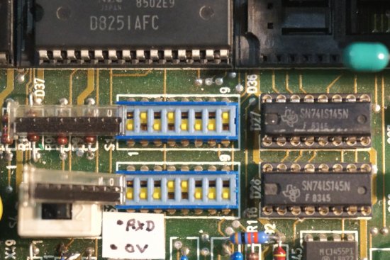
The Mainboard has some DIP-Switches (German: "Mäuseklavier") for multiple purposes. Two of them (S1 and S2) are only for binary pattern, recognized by an SN74145 BCD-to-Decimal Decoder.

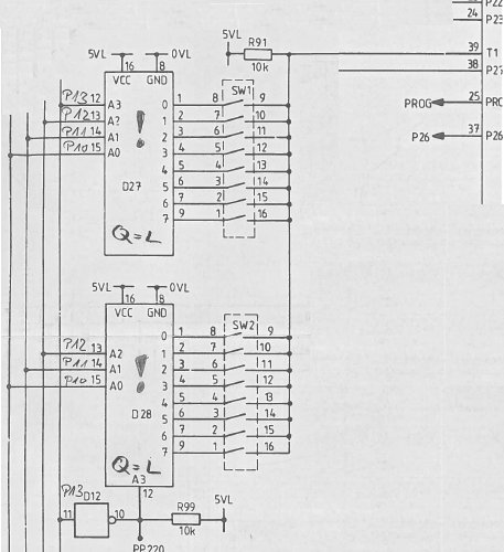
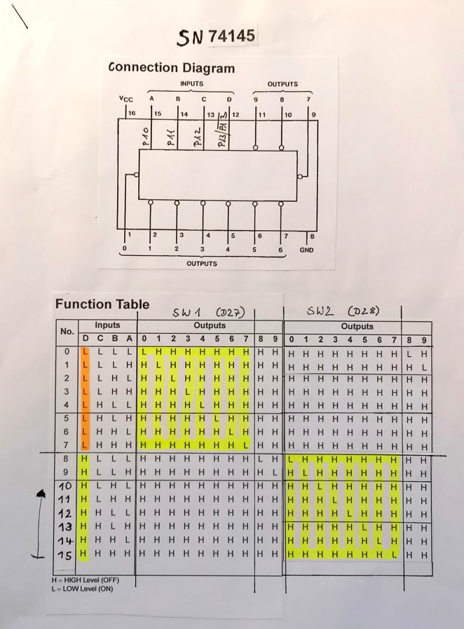
The decoder SN74145 will be addressed by P10-P13 (74145 Pin A-D) from the uC 8039 and the output (0-11) will be recognized the condition of connectors within of SW1 and SW2 by the uC 8039 pin T1. A closed switch will be seen as LOW and an open switch will be seen as a HIGH.


For the Proof of Concept SW1 will be used for the Adress and SW2 for the data, wich are send by the I2C routine.

See the SALEAE logicdata files for the Assembler file within the MC1000_I2C repository.
Custom Footer
MC1000 with Intel 8039